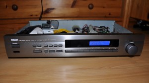
 Today I want to present you one of my larger craft projects. This time it is not just about software, but also about the associated hardware. What is it? A web radio!
I like to listen to internet radio stations, but I didn’t want to run my pc only for listening to webradios. Connecting my phone to my stereo either wasn’t a solution, since I’d rather wear this with me, because I don’t want to run for each SMS / Whatsapp message to the music system. And because I always like to tinker, it was obvious to build a web radio as a standalone device myself.
As this article has become a bit longer, there is a brief overview of the following sections of the article, so that everyone can quickly find what he looks for.
- What is the RadioduinoWRT?
- Considerations before building
- What should be the functions of the radio?
- Overview and parts list
- Configuration of the TL-WR703N
- The part around the Arduino
- The webinterface
- RadioduinoWRT on GitHub
- Photos of the radio
- Conclusion
1. What is the RadioduinoWRT?
The RadioduinoWRT is a self-designed and implemented webradio I built in the last weeks. So it’s a device that enables you to play your favourite internet radio stations. To give you a brief overview of how the finished product looks like and works, I have created a short video.
If any of you want to see more, you will find some pictures of the finished radio at the end of the article.
2. Considerations before building
Once the basic idea to build a web radio myself was fixed, I thought about the components to be installed. So initially I also included a Raspberry Pi to discussion. Finally, I have decided on a combination of the TP-Link WR703N router (about which I have already reported several times in my blog) and an Arduino Mega.
This decision had several reasons – first, I had both the router and the Arduino still in my parts box and on the other I wanted to implement the project as cheap as possible and on minimal hardware. Certainly a realization with a Raspberry Pi would have been possible, but this would have been more expensive than the TL-WR703N and the Arduino Mega together. Furthermore the hardware of the Raspberry is almost “oversized” for the project requirements.
3. What should be the functions of the radio?
Also in the beginning of the project I have worked out a list of functionalities that should be supported by the finished radio.
- Listening to internet radio streams
- Running without PC / standalone device
- Internet access over WiFi
- RCA output (for my amp)
- 16×2 LCD for displaying information
- Physical accessable menu
- Handling the device “with your fingers” must be possible
- Operation should be possible via optional IR remote control
- Web interface to control the radio from a PC or smartphone
All of these requirements were implemented during the project. Other features are not initially planned. If you, however, should have any good suggestions, I’m not averse to implement them and then add it to the article accordingly.
4. Overview and parts list
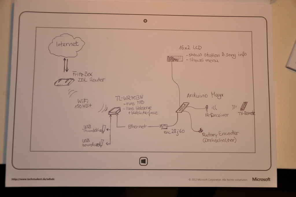
Once the requirements of the hardware and basic ideas were made, I have created a small sketch that defines how the later structure should look like.
The parts, that I have finally installed, are listed below. To help you find them on the internet, I set a link to the stores where I bought them for each one. (If any of the links do not work any longer, please send me a short comment below the article.)
- TL-WR703N mini router (~21$ @ Amazon)
- USB hub (~3$ @ Amazon)
- Nano USB thumbdrive (4GB für ~10$ @ Amazon)
- USB soundcard (~1.80$ @ Amazon)
- >0.5m audio jack extension (~2.20$ @ eBay)
- Audio jack to RCA Y-connector (2.40$ @ eBay)
- Defect (Yamaha) radio (because of the housing) (~5-15$ @ eBay)
- Arduino Mega Rev. 3 (~20$ @ eBay)
- enc28j60 ethernet module (~4$ @ eBay)
- IR receiver (~2$ @ eBay)
- Rotary encoder (~4.50$ @ Conrad.de)
- 16×2 LCD (16 Spalten, 2 Zeilen) (~2.60$ @ eBay)
- Cable / wire (from the tinker box)
- Breadboard (~1.65$ @ eBay)
- 0.5m LAN cable (~1.65$ @ eBay)
All together it cost about $ 99. At a first glance this looks a lot, but most of you will probably have some parts even in your own workshop or in the junk box. For example, almost everyone has floating around a USB thumbdrive eventually somewhere…
5. Configuration of the TL-WR703N
If all parts are provided, we can start with the configuration of the TL-WR703N. On this should run MPD as a music server and a also a web server. Therefore, however, the original Chinese firmware must be replaced by OpenWRT one. Then the memory of the router needs to be expanded using a USB thumbdrive, so that there will be enough space for MPD, the web server and the web interface.
I have already described in the following two articles how to get the TL-WR703N flashed with OpenWRT and to extend its memory (keyword: ExtRoot):
After you have followed all steps which are described in both articles above, let’s go on to the router setup.
5.1 Installation of the sound card
Turn the TL-WR703N off, if it is turned on. Remove the USB flashdrive, which you have plugged in during the ExtRoot tutorial. Instead plug the USB hub into the router and then plug the USB flashdrive and the USB sound card into the hub.
Now turn your TL-WR703N on again, login in via SSH on the router and enter the following commands (one command per line):
root@OpenWrt:~# opkg update
root@OpenWrt:~# opkg install usbutils
root@OpenWrt:~# lsusb
After entering the last command (“lsusb”) all USB devices should be listed. Here the USB sound card should also be visible. Now enter another command:
root@OpenWrt:~# cat /proc/asound/cards
Here the sound card should now also be listed and recognized as such. Instead the card will not be found. You have to enter the following commands so that the card is correctly recognized as a sound card in the system.
root@OpenWrt:~# opkg install kmod-usb-audio
If we enter the “cat/proc/asound …”-command again, the sound card should be displayed correctly.
5.2 Install MPD and MPC
In the next step, we will install MPD and MPC. MPD stands for Music Player Daemon and is a software that can play both music files and music streams. MPC is a console-based control software for MPD.
root@OpenWrt:~# opkg update
root@OpenWrt:~# opkg install mpd mpc
In order to make everything run, three directories must be created and a few small changes to the configuration file of the MPD have to be made.
root@OpenWrt:~# cd ~
root@OpenWrt:~# mkdir .mpd
root@OpenWrt:~# mkdir music
root@OpenWrt:~# mkdir .mpd/playlists
root@OpenWrt:~# vi /etc/mpd.conf
Using the last command we open the configuration file of MPD. Here we scroll to the line “# An example of ALSA output:” and uncomment the following “audio_output”-block. The whole thing should look like this:
audio_output {
        type            "alsa"
        name            "My ALSA Device"
        device          "hw:0,0"        # optional
        format          "44100:16:2"    # optional
        mixer_type      "software"      # optional
        mixer_device    "default"       # optional
        mixer_control   "PCM"           # optional
        mixer_index     "0"             # optional
}
All other “audio_output”-blocks, also the OSS block, have to be commented out, if this has not happened yet. For this purpose, write a “#” at the beginning of each line you want to comment out.
The installation and configuration of MPD/MPC should now be completed so far. You can now plug in a pair of headphones into the USB sound card to check if everything works. After that you can enter the following commands in the console for testing.
root@OpenWrt:~# mpd
root@OpenWrt:~# mpc
volume:100%   repeat: off   random: off
With “mpd” you start the server and with “mpc” the client. If you’ve done everything right, then the client’s output looks like the above status bar (volume: 100% …). But we need to specify the url of a web radio and set the MPD to play it to verify whether a web radio can be played.
root@OpenWrt:~# mpc add http://funkhaus-europa.akacast.akamaistream.net/7/264/119440/v1/gnl.akacast.akamaistream.net/funkhaus-europa
adding: http://funkhaus-europa.akacast.akamaistream.net/7/264/119440/v1/gnl.akacast.akamaistream.net/funkhaus-europa

root@OpenWrt:~# mpc play
http://funkhaus-europa.akacast.akamaistream.net/7/264/119440/v1/gnl.akacast.akamaistream.net/funkhaus-europa
[playing] #1/1   0:00/0:00 (100%)
volume:100%   repeat: off   random: off
Now you should hear some music from “Funkhaus Europa” on your headphones. Otherwise, scroll up a bit and see if you previously might have overlooked something in this tutorial.
More commands for the MPC can be found here.
6. The part around the Arduino
The Arduino represents the interface between the TP-Link router and the user. It connects all hardware parts, the rotary switch, the lcd display, the infrared interface and the web interface, with the MPD/MPC on the TP-Link router.
The most difficult part on the implementation was to handle both the long and informative texts on the display, as well as the Ethernet port, while having just very little memory available on the Arduino. Initially there were a lot of memory overflows. Finally, however, everything runs smoothly.
Since the source code for the Arduino became a bit longer, I will not explain every single line. Whoever has questions is welcome to write a comment. The pin assignment of the individual components on the Arduino is clear from the source code. Again anyone who has questions is welcome to write a comment.
7. The webinterface
We need an interface so that the Arduino can communicate with the WR703N,. For this we need a web server on the Tp-Link router. (Even if you do not want to have the web interface for the browser, you have to install a web server – otherwise the Arduino can’t talk to the MPD/MPC).
As web server I chose “Lighttpd”, since it is very resource-efficient. There follows the installation of LigHTTPD on the TP-Link router next. For this we have to log in via SSH on the TP-Link again.
root@OpenWrt:~# opkg update
root@OpenWrt:~# opkg install lighttpd lighttpd-mod-cgi
After the installation we have to change a few settings.
root@OpenWrt:~# vi /etc/lighttpd/lighttpd.conf
If the config file is opened, tweak the following settings.
# activate the mod_cgi module
server.modules = {
   [..]
   "mod_cgi"
   [..]
}

# add .php to the index file list
index-file.names = ("index.html","default.html","index.htm","default.htm","index.php")

# set up the web root directory
server.document-root = "/www_ext/"

# set up the server's port
server.port = 8080

# add the cgi path
cgi.assign = ( ".php" => "/usr/bin/php-cgi" )
Now you can save the lighttpd.conf file and close it. In the next step we will create the web root directory and start LigHTTPD as a service.
root@OpenWrt:~# mkdir /www_ext
root@OpenWrt:~# /etc/init.d/lighttpd enable
Now we need to tell the web server how to handle PHP files.
root@OpenWrt:~# opkg install php5 php5-cgi
After the installation, we need to specify the web root directory here yet.
root@OpenWrt:~# vi /etc/php.ini
doc_root = "/www_ext"
Now we are done with the installation of the web server. Finally we have a PHP enabled web server. As a minimum, we now need the PHP interface between Arduino and MPD/MPC. Therefore create a file called index.php in the “/ www_ext” folder.
root@OpenWrt:~# cd /www_ext
root@OpenWrt:~# vi index.php
Then copy the following PHP code into it.
If you want to have the web interface for the web browser in addition to the Arduino interface, you also need the “index_web_api.php”-file and the folder “webradio” including all files. The script and all associated files can be found in RadioduinoWRT GitHub repository. More in the next paragraph.
8. RadioduinoWRT on GitHub
All source codes for this project can be found in my GitHub account. There is a repository named “RadioduinoWRT” which contains the source for both the Arduino and for the (web) interface.
RadioduinoWRT @ GitHub
9. Photos of the radio
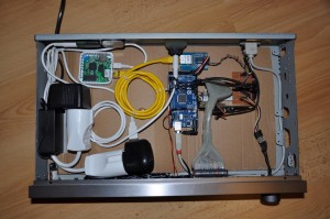
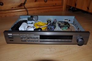
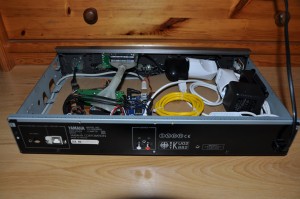
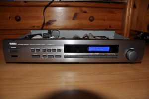
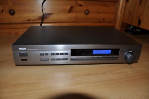
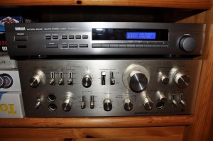
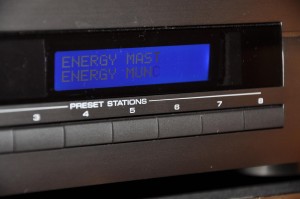
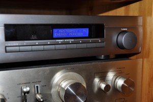
As initially promised, here are a few more pictures of the radio. Should you want to see something special or some more details, drop me a comment and I will deliver the desired photo.
10. Conclusion
The web radio was my first real project with the Arduino. Sure, I’ve already prepared small circuits, but until now I have never built “a real product” out of it. In between I was about to give up and jack it all in, because I had really problems with the limited memory of the Arduino and its rather weak debugging options. But finally I got it to work and I’m also a little itty bit pride to have arrived.
Certainly an experienced hobbyist/(hardware-)hacker would have done it more professionally, but you may not forget that this was my first bigger project.
What I definitely take with me, is that we should overcome our inhibitions against new technology and that such projects are doable with enough stamina, ernegy and good will.
I hope you enjoyed reading the article. If you still have questions, suggestions or tips, I would appreciate your feedback!



really great. still works for me!
Thanks to share your great Project. I started it and I hang out to 8. step.
I want to try control web interface from pc before ardunio interface. But I dont understand Can I run the webinterface.
And How can I Access to embeded index.php in the router?
Hi,
I am trying to build your great project on my own.
I would like to implement the feature with the IR-Remote. But I couldn’t locate the part in the Arduino Sketch can you upload the correct sketch.
Greate work, by the way!
Wow , thats awesome building m8. Congratulations. You”ve got MacGyver skills level ASIAN lol. Keep up the good work.
Oh, just out curiosity, do you code on python too?
Just wrote 2-3 scripts in Python, but I like C#, PHP, Java and JS more…
hi! sorry about my english! an altervative router than 703N ? could be tplink 3020? work ?? I can´t find this router
Yes of course , they are the same but tp-3020 have more outputs for led
Hey man, great work.. I’ve had this project on the back burner for a long time now..
I actually built everything and it all runs well except the arduino..
for some reason it’s pulling the index of luci instead of the index.php on ht lighttpd server
I see the one line of code : int beginMsg = msg.indexOf(P(“lighttpd/1.4.30”));
Isn’t the wr703n supposed to return the index page of the lighttpd server?
it’s not.
Ahh I figured it out…
you forgot to add in the port.
ether.hisport = 8080;
all better!
Thanks for the advice! :-)
awsome!
Failed to load database: Database corrupted
db file “/var/.mpd/database” is not a regular file
Why “var”? In the mpd.conf it is written “~/”” but it does not want to see my home folder…
mpc gives answer: refused connection :(
mpc refuses the connection because mpd isn’t running correctly. So at frist you should get the mpd running.
Hm I can’t remember if I changed the database path, but I think I didn’t so I can just guess the reason for your problems. I have two ideas:
1) Wrong user-context? Did you create the database/folders in homedir of user1 and start the mpd as user2? In this case mpd would search in another homedir.
2) The error says “/var/.mpd/database” maybe it’s a fallback because you specified a wrong path. Did you really wrote “~/database”? If so, add an file extension. For example “~/database.db”. Otherwise mpd thinks it’s an path but it expects a database-file.
There is only 1 user on router – root. MPD allready search in /root/.mpd ,but it says that data base file is corrupt. How can i fix it?
Ok, have you tried to recreate the database by executing “mpd –create-db” in shell?
root@GL-iNet:~# mpd –create-db
Failed to open –create-db: No such file or directory
Oh, WordPress throw of the command. It’s
"mpd --create-db"whereby the chars before create-db is a double hyphen:--mpd –create-db
** (mpd:2398): CRITICAL **: option parsing failed: Unknown option –create-db
mpd now does not know this option :(
I shall repeat this project with the housing of an old DVD. Can anybody give me an information about how to make the electronic part of project (arduino + lcd + ir-receiver + rotary encoder)?
/etc/init.d/lighthttpd enable must be
/etc/init.d/lighttpd enable
otherwise says not found
Thanks for the advice. I corrected it in the article.
hi ! Can i use for this project ARDUINO ETHERNET ? insted of mega ?
Ich think this won’t work. I also started with an Arduino Uno but had to switch over to an Arduino Mega, because of its SRAM. The Mega has four times more SRAM than the Arduino Ethernet, so I think it won’t work.
Ho trovato questo blog su google, sto leggendo con gusto tutti i post che riesco… il blog e’ semplicemente fantastico, complimenti.
Hi,
I am trying to build your great project on my own.
I would like to implement the feature with the IR-Remote. But I couldn’t locate the part in the Arduino Sketch.
Maybe I’m blind, but if not :-D could you provide the part.
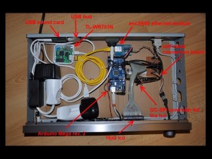
And in the pictures with the descriptions you are mentioning an I2C-SPI Controller for the LCD.
What is the purpose of that board?
Again great Job with this Project, I really appreciate the work you did!.
You’re totally right. Seems that I’ve uploaded the wrong version of the Arduino sketch. Unfortunately I’m not at home until next monday. So before Monday I can’t look for the correct Arduino sketch.
The I2C controller converts the SPI signal to the signals the Display needs. So normally you would need at least 6 pins on the arduino to drive the display. With the I2C expander you only need two. For more information have a look a this:
http://learn.adafruit.com/i2c-spi-lcd-backpack/
Thanks for the clarification and the link.
I’ll try to implement that function on my own.
I’ve have some time over the holidays. When I have problems I’ll look back at gitHub.
Frohes Fest! ;-)
Hi, can you upload the correct sketch.
I’m stuck on the part with the Remote Ctrl!
i would like to have a look at how you solved the problem!
Greate work, by the way!
Keep up the very good work.
I can ask for a wiring diagram for Arduino?
Sure you can! Sadly I’ve to tell you, that something like a wiring diagram doesn’t exist. I hacked the radio together and completely forgot to document the most things.
Nice, really well looking build.
Only a remark. If you connect the router and Arduino through serial connection you can avoid the usage of enc28j60 and the huge IPstack problem on the Arduino side.
George
I’m planing a similar project but with local music instead of webradio stations. you should take a look on the carambola2!
It runs with openWRT and has several GPIO pins, so you could replace the tp-link and the arduino with one single device.
Thanks for the tip! The carambola2 looks really interesting!
Have you already started your music player project? If so, do you plan to write about on a blog or website? (Because I’m really excited to see what your built looks like and how it works exactly.)
I’m planing to use a usb dac like this http://www.ebay.de/itm/160945208556?ssPageName=STRK:MEWNX:IT&_trksid=p3984.m1497.l2649 with a TI PCM2704 and the carambola. i have no blog or website to report about this.
I am currently looking for a suitable housing for the components.
Very Nice!!! great!
Change your USB Radio with a DAB Adapter to improve your device! ;-))
http://www.amazon.com/NooElec-RTL-SDR-RTL2832U-Software-Packages/dp/B008S7AVTC/ref=sr_1_4?s=electronics&ie=UTF8&qid=1383688079&sr=1-4&keywords=dab+radio