 Today, there is again a small Arduino craft project. This time, following the motto: “Soon it will clap, but no applause!” Because when you’ve finished reading the article and clap your hands, then your lamps should switch on and off.
The project originated from the (presumably nerd-specific) “emergency”, in which I found myself for some time and which looked like this: You want to go into the bed at night, but firstly you must turn on the light of the bedroom to be able to find the switch of the bedside lamp. Then you switched on the bedside lamp and run to the bedroom’s door again to turn off the bedroom light. You already notice the bedroom light is really just a means to an end.
As a clever computer scientists and hobbyists, one feels as though their relentless drive to optimize the process “light on” and so was born the following fine-tuning on my bedside lamp.
Now, when entering the bedroom, I can directly turn on the bedside lamp using dual clapping and thus save myself the unnecessary way to the bed and back again to the door to turn off the bedroom light. That may sound like a merciless laziness and I can already see the first of you throw your hands up in despair, but it is here primarily to the tinkering that warms my nerd heart.
DIY clapper (clap switch) – What do you need for it?
Now, to build such a construction, we need only a handful of (relatively) cheap components. For my setup, I have used the following parts:
- Arduino Nano v 3.0 (ATmega 328)
No products found.
- Arduino Sound Sensor / LM393
No products found.
- Arduino Relay Board
No products found.
- Various cable / jumper from the junk box. e.g.:
No products found.
In addition to that, we need the following tools:
- Wire cutter
No products found.
- Soldering iron
No products found.
- Knife
No products found.
All in all, makes around 25.00 $ and it is thus almost 9 $ more expensive than the ready-to-use clapping switch from Amazon for 16 $. But if you can wait 1-2 months for the parts, you can order them on eBay directly from China and then the costs will fall to around 12 $ for everything together, which brings us back cheaper than the convenience product.
Not to mention, that this tutorial is driven by primarily for the fun of building something yourself instead of creating the most favorable possible product.
Physical setup of the Arduino for the clapping sensor
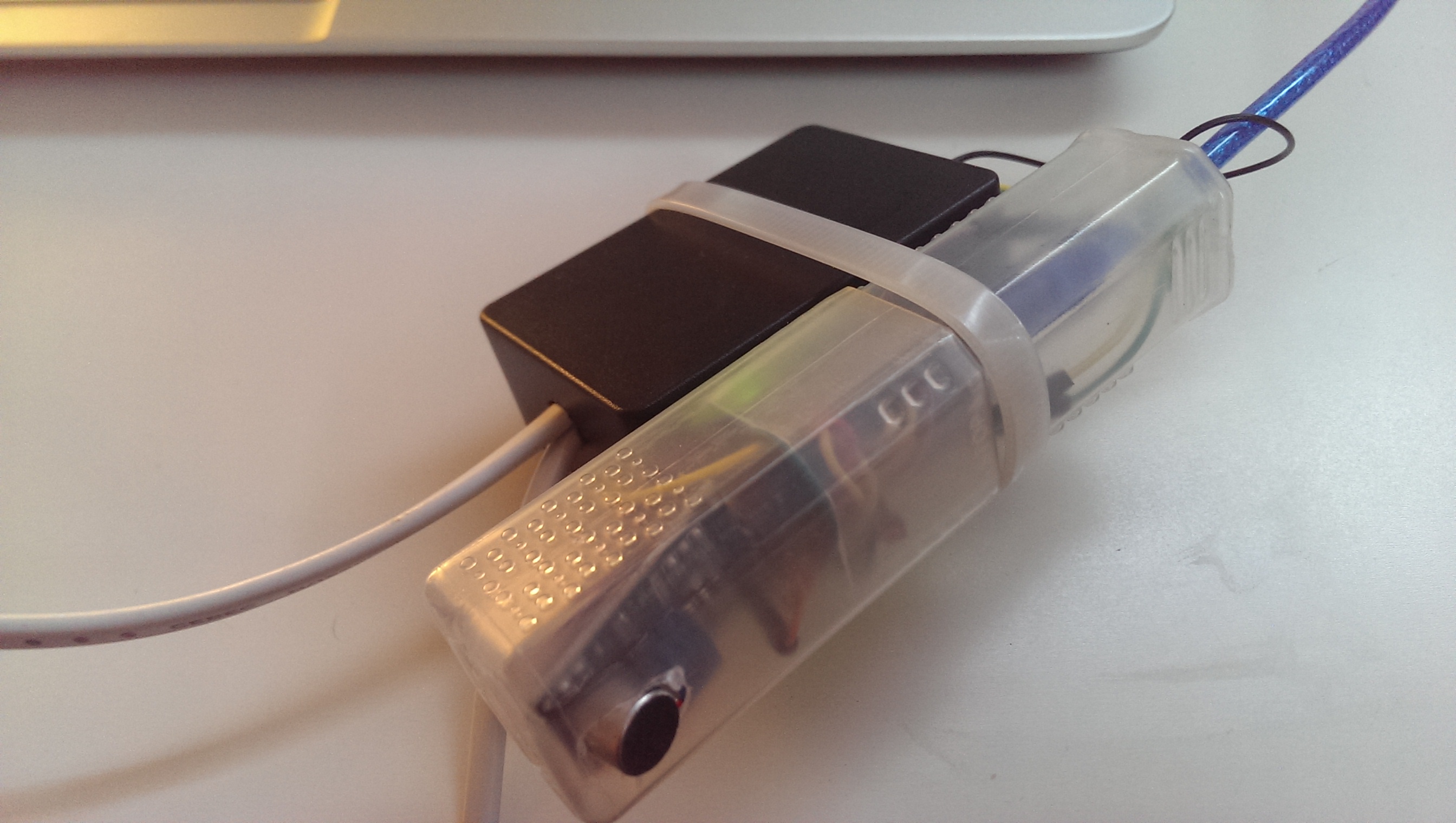
When you have collected all the parts, you can start to build up. Due to the small number of components, the clutter is limited. (No comparison to my Arduino radio.)
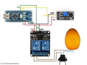
Before you get started, just a bit of theory and a few words about how to build. The Arduino shall listen via the connected “Sound Sensor” systematically whether a particularly high volume level (=peak) is present. This peak is generated by you due clapping your hands. If this peak occurs 2 times in a given period of time, the Arduino switches a relay, which then turns on the connected bedside lamp. Due to the relay and the photocoupler on the relay board we also achieve a galvanic isolation between the microcontroller and the bedside lamp.
More about the program logic will follow in a later section of the article. Now it’s time for the wiring. The figure ahead and the following table should be self-explanatory. If you still have questions about cabling, let me know in the comments.
| Arduino Nano | Sound Sensor |
| 5V | +5V |
| D3 | OUT |
| GND | GND |
| Arduino Nano | Relay Modul |
| 5V | VCC |
| GND | GND |
| D4 | IN2 |
Programming the clap recognition on Arduino
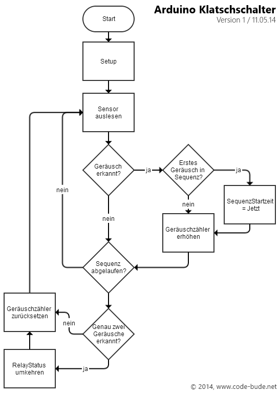 Now that all wires are connected and the soldering iron should cool down, we come to the programming. We have already made a few basic ideas initially. The program should therefore perform the following tasks: Reading sensor to determine if there is any clapping. Mark and save claps and when clapping was twice, switch on or off the light. In order to visualize the whole, I created a small program flow chart for this, which you can see on the left side.
There is one little tweak as to the rest really simple sequence. If the sound sensor detects a noise that is louder than a preset level, then it writes a 0. So if I scream 1 second at a stretch, the sensor also triggers at least twice so that the light would come on. How can we distinguish between someone has clapped twice (=two single peaks) and our vacuuming neighbour?
To clarify this issue, let us have a look at what a microphone records when we clap. For this I have made two records with the freeware Audacity, while I clapped twice each. One time faster, one time more slowly clapping. I have done this, because in practice we clap not always exactly the same pace.
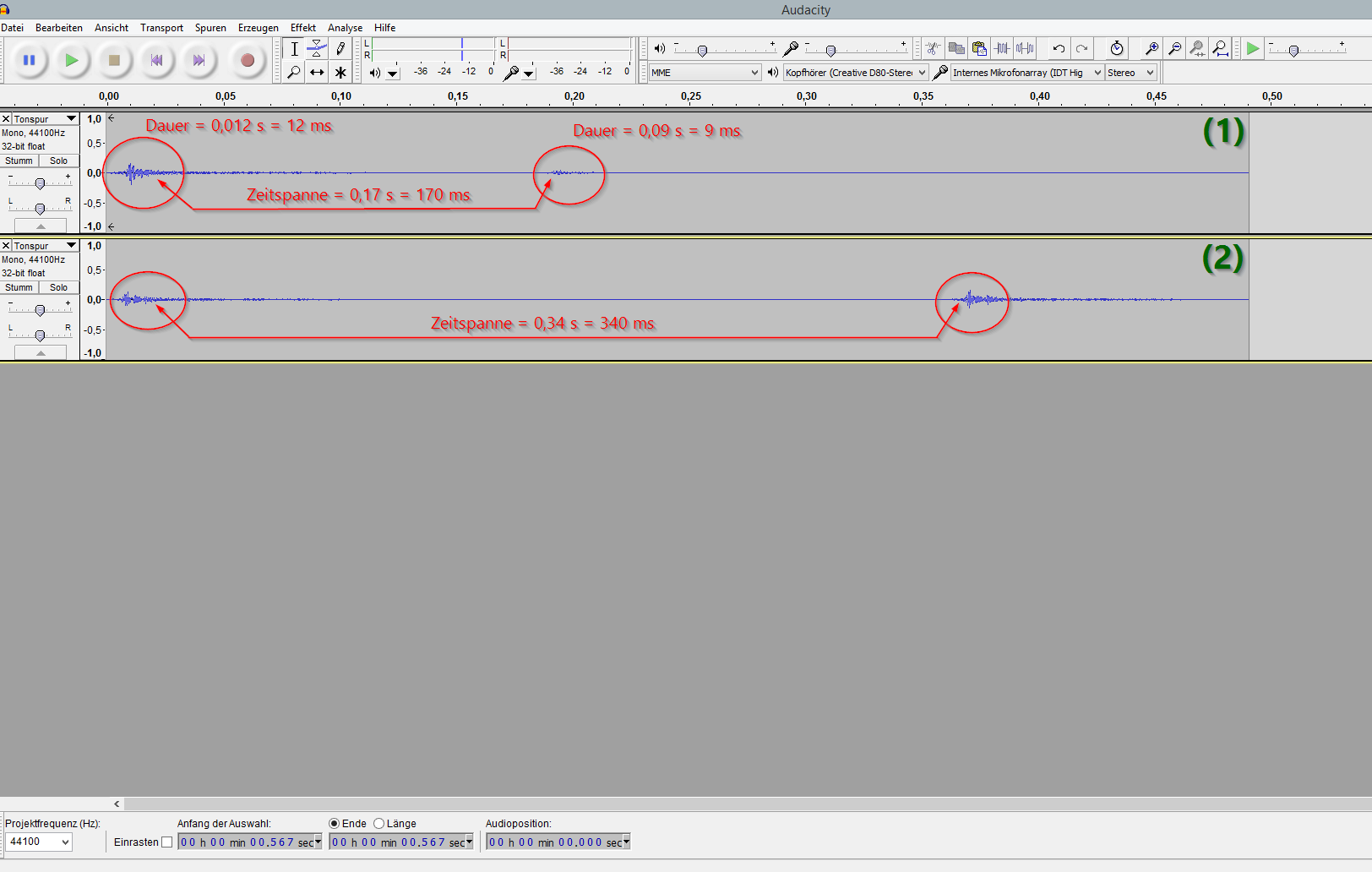
Now, the recordings can be considered in Audacity in more detail. On the basis of the level diagram, we can see how long a “clap” takes and how much time passes, until you clapped twice. (Also adjacent figure serves to illustrate.)
We can see that the fast twice clapping takes about 170 ms and the slow clapping takes 340 ms. Now let us add some tolerance, so that we can say that our “double-clap” is dealt within 400 ms. Now we take this as sequence length for the above program flow chart. So we count all peaks (volume level peaks / trips) for 400 ms and then see if exactly two peaks were found. If our neighbour was going to vacuum, then the number of peaks would be much higher during the captured 400 ms sequence. Thus we can distinguish whether someone clapped (or knocked/whistled/screamed) twice or if any other noise source has tripped with continuity.
The source code
Now that we have covered the build-process and the logic behind the program, only the “sourcecode question” remains open. This one should be pretty self-explanatory after all the information you got. But if there are questions about the source code, just add a comment to this article.
int soundSensor = 3;
int relay = 4;
int claps = 0;
long detectionSpanInitial = 0;
long detectionSpan = 0;
boolean lightState = false;

void setup() {
  pinMode(soundSensor, INPUT);
  pinMode(relay, OUTPUT);
}

void loop() {

  int sensorState = digitalRead(soundSensor);

  if (sensorState == 0)
  {
    if (claps == 0)
    {
      detectionSpanInitial = detectionSpan = millis();
      claps++;
    }
    else if (claps > 0 && millis()-detectionSpan >= 50)
    {
      detectionSpan = millis();
      claps++;
    }
  }

  if (millis()-detectionSpanInitial >= 400)
  {
    if (claps == 2)
    {
      if (!lightState)
        {
          lightState = true;
          digitalWrite(relay, HIGH);
        }
        else if (lightState)
        {
          lightState = false;
          digitalWrite(relay, LOW);
        }
    }
    claps = 0;
  }
}
Conclusion
Well, the article has become a little longer than expected. Nevertheless, the technical design and the source code is quite simple, so that it is legit to claim that expanding a lamp with a “clap” function is possible without great effort.
What do you think of the project? Do you have questions, comments or suggestions for improvements? Let me know!

The code works just fine
But I have a problem if I put any block of code under this code or above it like printing hi the sound sensor code doesn’t work why is that?
Hello I’m a beginner and just don’t know how to modify this code for 2-way relay anyone can explain please???
else if (claps > 0 && millis()-detectionSpan >= 50)
{
detectionSpan = millis();
claps++;
Can you explain more about this part? What does it mean about 50 in that code?
Hi Brian,
this part of the code is for “debouncing”.(See: https://en.wikipedia.org/wiki/Switch#Contact_bounce)
Explanation: We are inside the “sensorState == 0”-clause. This means the sensor got a noise (possibly a clap). No we decide between the first clap (claps == 0) and every other clap (claps > 0 && millis()-detectionSpan >= 0). But why do we do so?
If we get the first clap, we do two things. We raise the clap-counter by 1 (claps++;) and we set detectionSpanInitital and detectionSpan to the value “millis()”. The millis-function returns the time in milliseconds since the Arduino powered on.
Now let’s say we clap the second time. The code would skip “if (claps == 0)” because claps is already raised to “1”. Now the code checks “if (claps > 0 && millis()-detectionSpan >= 50)”. First part (claps > 0) is true, because claps is 1. The second part (millis()-detectionSpan >= 50) takes the current runtime in milliseconds (millis()) and subtracts the time when the first/last clap was registered (detectionSpan). Then it compares the outcome (namely the time since the last clap) and checks if this is longer away than 50 milliseconds.
Why do we do so? A human can’t clap twice within less then 50 milliseconds. So we don’t do this, because someone could clap too fast. But there’s another possible problem. If you clap one time, your clap echos for 10-30 milliseconds. If the arduino’s code runs that fast, that it checks the microphone every 10 milliseconds it would register 1-3 claps, even if you clapped only one time. That’s why we pass this artifical “delay”. (That logic is called “debounce”. See the link above.)
I hope I could clarify things a bit. If not, let me know.
does not work from distance… no matter if we align the mic or not. Simply works only if i clap near the mic…. (already played with the potentiometer on the mic…
Hi deniz,
sad to hear, that it doesn’t work for you. Maybe you got an “faulty” microphone-board? I can only speak for my setup, so this isn’t valid for anyone. But my setup works over a distance up to 5-6m without any problems.
@Raffi, Thanks for the nice work and tidy write-up!
I notice that you’ve used a timing based method to detect claps.
To increase your accuracy, you could additionally use a frequency based method.
From https://learn.adafruit.com/adafruit-microphone-amplifier-breakout/measuring-sound-levels
You can see how to measure sounds at certain frequencies.
With a bit of work, one could work out the dominant frequencies in a clap (i imagine they’d be fairly constant), using audacity again, and adjust the existing sketch to tune/filter the frequency detected.
I’d love to have a go, if only I had the time!
Thank you very much for this tutorial :-)
Hi Raffi,
nice tutorial. There’s a possibility to simplify the code.
In digitalWrite you can also use a boolean flag directly instead of HIGH or LOW.
So instead of this:
if (!lightState)
{
lightState = true;
digitalWrite(relay, HIGH);
}
else if (lightState)
{
lightState = false;
digitalWrite(relay, LOW);
}
you can write this:
lightState = !lightState;
digitalWrite (relay, lightState);
(I didn’t try it, but it should work IMHO)
Regards, Stefan
PS:
see https://www.arduino.cc/en/Reference/BooleanVariables
how do you increase the amount of sound the sound sensor picks up
You have to tune the sensor sensitivity trimming the on-board trimmer. Read the OUT pin of the sensor board with a DigitalRead via Arduino and look if the state changes from 1 to 0 (or vice versa) using the Serial Monitor. Then tune the trimmer again until you find the best position based on the sound level you’re looking for.
Could you explain how can i adjust the sensitivity and monitor the state ?
I add a line “Serial.println(sensorState);” and i only got 1. does it means that my sensor is too sensitive ?
Sorry but i am not familiar with trimpots and how it works.
Hi Raffi,
thanks for this tutorial. Very helpful!
Actually I’ve an ‘Arduino Due’ that works with 3.3V logic. So I’m facing difficulties to discover the right potentiometer position in order to read exactly two consecutive values because the digital level thresholds are very close each other. Sometime relay suddenly switch on or off but not simple to replicate certainly!
Moreover I applied 3.3V Arduino supply to the Vcc of the sound sensor to help having quite same voltages.
Do you have any idea? Do you think could the code be improved to catch the claps?
p.s. Arduino Due has a cons having 3.3V as logic supply but on the other side has a pros letting you learning by difficulties!!
Thanks.
int soundSensor = 3;
int relay = 4;
int relay2 = 5;
int claps = 0;
long detectionSpanInitial = 0;
long detectionSpan = 0;
boolean lightState = false;
void setup() {
pinMode(soundSensor, INPUT);
pinMode(relay, OUTPUT);
pinMode(relay2, OUTPUT);
}
void loop() {
int sensorState = digitalRead(soundSensor);
if (sensorState == 0)
{
if (claps == 0)
{
detectionSpanInitial = detectionSpan = millis();
claps++;
}
else if (claps > 0 && millis()-detectionSpan >= 50)
{
detectionSpan = millis();
claps++;
}
}
if (millis()-detectionSpanInitial >= 400)
{
if (claps == 2)
{
if (!lightState)
{
lightState = true;
digitalWrite(relay, HIGH);
digitalWrite(relay2, HIGH);
}
else if (lightState)
{
lightState = false;
digitalWrite(relay, LOW);
digitalWrite(relay2, LOW);
}
}
claps = 0;
}
}
How to do that in two clap turned relay first and then the three of clap second relay? This is code to the fallen of both relay at the same time. Thank you,works great!
Add ” boolean lightState2 = false; ” in the heading. Then change the following part:
if (millis()-detectionSpanInitial >= 400)
{
if (claps == 2)
{
if (!lightState)
{
lightState = true;
digitalWrite(relay, HIGH);
}
else if (lightState)
{
lightState = false;
digitalWrite(relay, LOW);
}
}
if (claps == 3)
{
if (!lightState2)
{
lightState2 = true;
digitalWrite(relay2, HIGH);
}
else if (lightState2)
{
lightState2 = false;
digitalWrite(relay2, LOW);
}
}
claps = 0;
}
}
Thank you very much … now it is clearer
hi, can you tell me if this circuit needs any kind of power supply?
You have to power the arduino. Either by using a USB power adapter or a generic power source.
Hello Miško, I can certify that it works very well, the only problem is to adjust well the sensitivity of the microphone, or you will have to clap too loudly.
Also, with high rapid sounds like 2 coughs, it is activated too, so be aware if you have catarrh :)
clap switch using Arduino
Can you tell me if this project works 100%?
Thank you very much, you saved me a lot of time!!
Sometimes with this simple code there are false activations (due to the low quality of the microphone sensor); with a timeout of 6 hours for example you avoid long activation times (or using an ultrasonic sensor HC-SR04 for detecting previous human presence).